
Tips for Managing your Project’s Increasing Complexity: Part 2
 Herman Bruyninckx via Wikimedia Commons
By SSI Fellow Dr Edward Fisher, Firmware Development Group, RADAR Electronics, Leonardo MW Ltd.
This is the second part of this blog post, see part one here.
Tip 4: The Project Lifecycle:
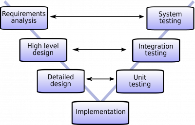
As an aid to developing complex projects, systems engineering utilises a common product life cycle. However, this is best viewed as an onion, with each phase having a set of inner steps. The overall stages are:
- Needs Analysis: Start by defining, quantifying and agreeing why the project is needed. What goal does it serve? This helps focus the team and defines the scope of work. Full agreement early in the project is a significant advantage.
- Requirements Analysis: The need allows definition of the main project requirements. What does it do? What are its inputs, outputs and controls? What external factors might impact it? View it as a black-box process to consider requirements for what it needs to do within it. Check the list is provisionally complete against everything for the need identified then ensure full team agreement. If you need to make any updates, do this in a formalised way through agreement and a shared “master version”.
- Concept Definition: For each requirement, how could this be achieved in a realistic timescale and budget? View this as a tree search, exploring all branches, consider interactions and trade-offs between requirements and use the power of the team to generate ideas and alternatives. Document all of these and what technical discipline is needed, as even unused concepts may form contingency plans later in the project. Check all requirements have at least two possible concepts for their solution. Again, get agreement that everyone on the team is happy with the possibilities and have had the opportunity of contributing ideas. Distribute a “master version”, so that even someone of a radically different specialism (chemistry vs software) can see what the general solution space looks like.
- Concept Feasibility and Trade-Off Analysis: Try to assess the feasibility and likely risk involved with each branch of the tree. Perhaps for one requirement, there are two possible solutions, but one is far more expensive than the other? For another, perhaps design incurs significant risk? If so, how could that be mitigated? Start to make choices as to which of the possible solutions is most likely to succeed. Consider their relative risks, costs and prerequisites. If there are any trade-offs, discuss them and decide which side should be given priority. The end of this stage should provide a team-agreed overall conceptual design that is highly likely to succeed. Agreement is crucial as it aids collaboration but also you will find that deeper technical details and requirements will be based on these choices.
- Functional Allocation and Work Breakdown Structure: With a feasible concept described for each system requirement, the requirements can be collected into logical groupings. This is the start of a functional block diagram that again can be agreed over the entire team. Also consider which technical discipline (or team member) would do the work for that requirement. This allows checking for any asymmetry of team member workload, agreement as to scope of work, and starts the process whereby top-level requirements flow into block-specific or technical discipline specific requirements documents. When you agree to this stage, consider it a contract of what is expected of each collaborator, their deliverables and acknowledgment their work will interact with the work of others.
- Engineering Design: The above requirements, concept definition and allocation in a block diagram can be repeated for each block in the top-level diagram. Use the requirements for one particular block as the source for lower level requirements. This ensures requirements at every stage can be traced back to one that has been agreed at the top-level. Try to discover some of the unknowns early so they can be discussed. If a concept or requirement in a previous stage needs to be changed, it is always cheaper to do this earlier than later.
Allocate the derived requirements into functional blocks to form a block diagram at this level too, as agreement within the block’s team can significantly aid collaboration. The hierarchical block diagramming method here directly aids modularity in the implementation. This is especially useful when it comes to testing, identification of where an error occurred and tracking of time estimates vs project milestones. The end of this stage is a completed design for a block that has been functionally verified against all of its requirements, has been iterated to close any critical issues and has a full documentation deck.
- Integration, Evaluation and Testing: While blocks may have been tested and verified on their own, significant time can be spent ensuring correct behaviour when blocks are integrated together. Clear definition of the interfaces between blocks can aid this problem. Remember though, that it’s once the system comes together as a whole that it is truly able to address the project’s intended purpose. To verify and evaluate this, it is worthwhile employing a set of use-cases and error scenarios as part of a test suite. At its base, this test suite can also re-validate the integrated design against its requirements allowing a comprehensive design sign-off.
- Operation, Ongoing Support and Future Reuse: Projects rarely exist in isolation. Try to design with the future in mind, be it adding features or radically increasing performance. Remember that elements of the project may be re-used for following projects, after all, part of this flow has been to design and verify blocks with defined interfaces. A follow-on project may view the work as pre-verified intellectual property that it can use to significantly increase complexity. Also consider who will use it when it is deployed or when it is maintained. Not only does this imply documentation, it also implies documentation that focuses the project’s complexity for that user.
Take Home Messages:
There are four take home messages within this lifecycle.
- Each stage brings about an increased level of “materialisation”, i.e. the design becomes more defined as the process continues from concept, through its design, to a finished end output, product or deliverable.
- Each stage provides a set of requirements, in increasing detail. This creates a set of success criteria for the next phase.
- Each stage provides a verification opportunity against the outputs of the previous stage. For example, is the design functionally complete with respect to the functionality that was requested in the design’s requirements document?
- Each stage provides for a design review, where all issues can be discussed and cleared before proceeding. This maintains agreement within the team and forces decisions to be formalised. Feedback to a previous stage can also be included which allows top-level requirements to be expanded as more of the project’s detail is considered. These then flow down again keeping the project and documents coherent.
A significant advantage of this project flow is that agreement and documentation is comprehensible for all staff in the team and that there is an element of traceability back to original project requirements. The project becomes hierarchically documented such that there is a specific and enumerated reason why a function was implemented. This, and the listed requirements input into each stage, act to guide developers and reduce unnecessary work. The approach also ensures that the implementation does not include functionality that goes beyond the requirements, as this could add risk into the development process.
Further Reading:
The above tips are based upon the book: “Systems Engineering: Principles and Practice”, A. Kossiakoff and W. Sweet, Wiley Inter-Science, 2003.
The field of system’s engineering is large in its own right, with “Systems Engineer” being a function common in companies that develop highly complex systems. When you consider a modern car, the number of systems, sub-systems, components, interfaces and technical specialisms required is staggering. It is only through a managed approach that project complexity can be handled when we aim for an outcome that breaks current technical barriers.
A famous example is NASA and the management approach used for lunar exploration. Their dedicated systems engineering handbook is available here: https://www.nasa.gov/connect/ebooks/nasa-systems-engineering-handbook